Showing posts with label proteus. Show all posts

Tuesday, September 29, 2015

PROJECT 2b: Interfacing LCD 16x2 with AVR


Hey Guys,

Today lets discuss a basic output device. A LCD(Liquid Crystal Display) for your AVR's.
Its a nice and easy tutorial where you can learn to interface an LCD and display your bot status or any serially , Wireless received messages or anything from your ucontroller.

Soon i'll also share with you the files on how to do it on our 3 other favorite platforms:
1) Arduino
2) 805x series.
3) PIC controller


Lets look at the basic working of an LCD module. It receives data in ASCII format.


PIN DIAGRAM  and their uses:

VDD- +5v
VEE- power supply to contrast using a potentiometer
VSS- ground

RS-Register select (0=command code     1 = data word)

R/W-Read/Write    (0 = writing         1 = reading)

E- Enable (High to low pulse to latch data)

D0(lsb) to D7(msb) are data bits


Fig. A Basic LCD and its pins.


Some handy commands we will use:

0x01= clear screen
0x02= return home
0x04= cursor 1 place left
0x06= cursor 1 place right
0x05 shift display left
0x07 shift display right
0x0E= display on , cursor blinking
0x0f = display on , cursor blinking
0x80= force cursor to beginning of first line
0xC0= force cursor to beginning of second line
0x28= 2 lines 5x7 matrix(D4-D7, 4 bit data)
0x38= 2 lines 5x7 matrix(D0- D7, 8 bit data)

so suppose the LCD data bits D0 to D7 are connected to port C.1 to C.7

RS= PORTB.0

R/W= PORTB.1

Enable pin=PORTB.2

VDD- +5v

VEE- power supply to contrast using a potentiometer

VSS- ground


Below is the  basic circuit and different states of LCD on running the below program.


burn the demo code below to your AVR USING PROGRAMMER's Notepad and enjoy making minor twitches and interfacing your lcd with AVR.

*****************************************************************************************************


void delay_ms(unsigned int c)
{
_delay_ms(c);
}


void comm_write (unsigned char a)
{
   PORTD=0x01;
PORTC=a;
PORTB &= ~(0x03);
PORTB|= (1<<2);
delay_ms(2);
PORTB &= ~(1<<2);
delay_ms(100);
PORTD&=~(0X01);
}

void data_write(char* str )
{
unsigned char i=0;
while (str[i] !=0)
{
PORTC=str[i];
PORTB = PORTB & ~(0X02);
PORTB = PORTB |(0x01);
PORTB|=(1<<2);
delay_ms(200);
PORTB= PORTB & ~(1<<2);
delay_ms(200);
PORTB = PORTB & ~(0X03);
i++;
if (i>15)
{
comm_write(0x07);
}
}
}

void init_lcd()
{
DDRB=0Xff;
DDRC=0Xff;
DDRD=0x03;
PORTB &= ~(1<<2);
PORTD|=(1<<2);
delay_ms(2000);
PORTD&=~(1<<2);
comm_write(0x38);
comm_write(0x0E);
comm_write(0x01);
delay_ms(2000);
comm_write(0x06);
data_write("Abhirup.");
comm_write(0xC0);
data_write("welcome to my tutorials");

}

int main(void)
{
init_lcd();
return 0;
}


*************************************************************************************************

Have fun playing around. And feel free to ask questions around the circuit or code or its scope of use.

keep reading :)
Abheerup

Saturday, February 7, 2015

"HELLO WORLD" IN AVR - LED BLINKING & WRITING / SIMULATING YOUR FIRST PROGRAM

Hello & welcome to the first tutorial on AVR

This tutorial is focused on imparting basic AVR knowledge to folks interested in beginning in embedded systems & robotics.

The very first post is on the "HELLO WORLD" in robotics (specifically AVR).
I'd suggest you kindly clear your basics of digital electronics before starting this tutorial.
Also learn to read data sheets of basic IC's such as the following:


  1. 555 timer.
  2. max232
  3. opamp 741
  4. lm35
  5. adc0804
  6. ATtiny
& our first microcontroller  ATMEGA 16.
FOR beginning the set of tutorials, we'll download "WINAVR setup" & install it onto the desktop. & open the PROGRAMMER's NOTEPAD.


1) select file->new->c/c++ file to compose your first AVR program
2) write the given program & save it at a desired location in a separate folder

3) Now find the makefile & edit it.


4) to Edit makefile, select the desired F_CPU speed (Preferably 8000000 or 16000000) & also change the TARGET FILE NAME to the name of your own progam saved with programmer's notepad. & then save the makefile using File->save as on top left of makefile. SAVE THE MAKEFILE IN THE SAME FOLDER AS YOUR PROGRAM.C . 
5) After storing your own program file & makefile in the same folder. Click on Make Clean & Make All.
check for ZERO ERRORS in the dialog box below. & proceed.
Congrats, You have compiled your first AVR PROGRAM USING PROGRAMMER'S NOTEPAD.

6) Your project Folder will appear similar to this after step 5. It will have the "program.c" file as well as makefile & the "program.hex" file. & a bunch of other files whose use we'll discuss in the coming tutorials.

& Now , moving on to our next software Proteus. Its an animated software simulation method of your circuits.
Google this Software. You'll find plenty of good download links with FULL SETUP (SOFTWARE + CRACK+ LICENSE KEY). So Download & install the setup using the "HOW TO TEXT FILE".
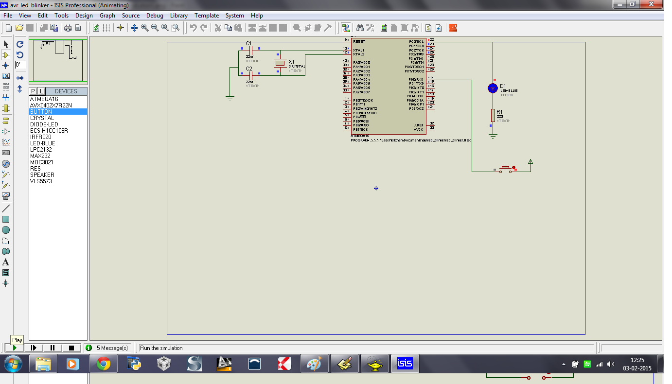
7)Using the part list library within Proteus. Make the connections & Construct this basic circuit. 
8) Save the design file for your ease in the same folder as your AVR project folder. I advise you make a folder for each project in the coming tutorials & save it with the title name of your project.
eg. :  LED_BLINKER_TEST folder
              > LED_BLINKER.c
              >LED_BLINKER.hex
              >LED_BLINKER.dsn
              >makefile


9)Now lets add the hex program to the Proteus circuit for software simulation. for that click
SOURCE->Add/remove source file-> & select the target processor as the microcontroller in the design. for our design we chose atmega16. & click new to select the source file . CLICK & SELECT THE .HEX FILE from the project folder & proceed.

10) Now after adding the Hex file to design. click Execute & the click on the green Play button on the bottom left to Simulate. & use pause/play/stop button as & when you require.
After following all steps properly, You'll see the Animated led glowing after a specific delay.


Next, we'll Focus On BURNING the program to a real hardware using AVRDUDE .
Open AVRDUDE GUI & make the following settings:
i.e set your controller(we are using atmega16), programmer/burner (i am using usbasb), com port(check for ComPort by looking into the device manager for New hardware. This will pop up everytime you connect a new controller/device to your pc ), high fuse & low fuse.
Select the hex file & execute.

As my device is not connected to the machine. you see the message below.


when you connect your device , you'll see it in the device manager.
while programming, select the same COM PORT (COM3 in this case ) while programming.


You may use a common AVR burner hardware & connect the controller on a development board or breadboard & program the controller to see the led connected to C- bit 1, blinking.


For all of you who are yet confused about the fuses , i'll do a separate comprehensive tutorial on 
  • AVR FUSES of some common AVR controllers.
  • TIMERS /DELAYS & INTERRUPTS
  • SERIAL & PARALLEL COMMUNICATION

Also feel free to ask any doubts regarding the projects.


-Abhirup :)